In the world of injection molding, achieving a perfect balance between strength, weight, cost, and aesthetics is paramount. One critical design feature that significantly impacts this balance is the rib. Ribs add structural integrity1 to plastic parts without dramatically increasing overall thickness. However, designing them incorrectly can lead to cosmetic defects and structural weaknesses.
A key parameter in rib design is the rib-to-wall thickness ratio2. Getting this ratio right is crucial for preventing common molding defects3 like sink marks and ensuring the part functions as intended.
At ZetarMold, we leverage decades of expertise in injection molding and silicone rubber products to help our international clients optimize their designs for manufacturability and performance. This guide dives deep into understanding and applying the ideal rib-to-wall ratio.
- 1. I. Basic Cognitive Level: Establishing Conceptual Framework
- 2. II. Application Analysis Level: Solving User Decision-Making Problems
- 3. III. Technical Deep Dive Level: Meeting Professional Reader Needs
- 4. IV. Practical Tools Level: Enhancing Content Operability
- 5. V. Extension Level: Building a Knowledge Network
- 6. Conclusion: Balancing Strength and Manufacturability
I. Basic Cognitive Level: Establishing Conceptual Framework
Before diving into the specifics, let’s define the core concepts:
-
Rib: A thin, wall-like feature incorporated into a part’s geometry, typically perpendicular to a main wall, designed primarily to increase stiffness and strength.
- Aliases: Stiffening Rib, Reinforcing Rib.
- Core Principle: To enhance structural performance locally without making the entire part thicker, thus saving material and potentially reducing cycle time.
- Nominal Wall Thickness4: The generally uniform thickness of the main body or surface of the plastic part to which ribs are attached. This is a foundational parameter in part design.
- Rib Thickness5: The thickness of the rib itself, usually measured at its base where it joins the nominal wall.
- Rib-to-Wall Ratio6: The mathematical relationship expressed as:
Rib Thickness / Nominal Wall Thickness. This ratio is critical for predicting and preventing molding defects.
Classification Perspective:
While the ratio itself isn’t classified, ribs can be categorized by:
- Function: Structural7 (load-bearing), Locating (alignment), Heat Dissipation (fins).
- Design8: Simple straight ribs, Gussets (triangular supports at corners/bosses), Networked ribs.
- Location: Internal (most common), External (less common, often for grip or aesthetics).
The choice9 of ratio often depends on factors related to material, aesthetics, and structural requirements.
II. Application Analysis Level: Solving User Decision-Making Problems
Understanding why and where this ratio matters helps in practical design decisions.
Typical Application Scenarios:
Ribs, and therefore the consideration of their ratio, are vital in:
- Housings & Enclosures: (e.g., electronics, appliances, power tools) – Providing rigidity and preventing flexing.
- Structural Components: (e.g., automotive brackets, furniture parts, support frames) – Increasing load-bearing capacity.
- Internal Features: Supporting bosses (screw mounting points), aligning internal components.
- Large Flat Surfaces: Preventing warping and improving flatness.
Pros and Cons Comparison (Optimal Ratio vs. Incorrect Ratios):
| Feature | Optimal Ratio (40-60% Wall Thickness) | Too Thick Ratio (>60%) | Too Thin Ratio (<40%) |
|---|---|---|---|
| Pros | Good balance of strength & moldability, minimizes sink marks, good fill. | Potentially higher stiffness (if sink is ignored). | Lowest risk of sink marks, fastest cooling of the rib. |
| Cons/Risks | Slight sink risk (material dependent), requires careful design. | High risk of sink marks, voids, warping, long cycle time. | May provide insufficient stiffness, potential short shots (incomplete filling), fragile. |
| Best Suited For | Most applications requiring strength without cosmetic flaws. | Applications where severe sink is acceptable (rare). | Applications where minimal stiffening is needed, or cosmetics are paramount. |
Why use Ribs instead of thicker walls? Compared to simply increasing the overall wall thickness:
- Pros of Ribs: Better strength-to-weight ratio, less material usage, potentially faster cycle times (if designed correctly), reduced risk of severe sink/voids found in very thick sections.
- Cons of Ribs: Increased mold complexity and cost, potential for sink/warp if designed improperly, potential stress concentration points if sharp corners exist.
The key takeaway: The optimal ratio (typically 40% to 60% of the nominal wall thickness) is a guideline designed to balance structural contribution with moldability, primarily avoiding sink marks.
III. Technical Deep Dive Level: Meeting Professional Reader Needs
Let’s explore the technical aspects relevant to professionals.
Process Full Workflow Breakdown (Rib Impact):
-
Part Design (CAD): Define rib geometry:
- Thickness: Target 40-60% of the adjacent wall. (Key Parameter)
- Height: Generally ≤ 3 times the nominal wall thickness.
- Draft: Minimum 0.5° – 1.5° per side (essential for ejection).
- Base Radii: Crucial! ≥ 0.25x – 0.5x wall thickness (minimum 0.5mm often recommended) to reduce stress concentration and improve flow.
- Spacing: Distance between ribs should be ≥ 2 times the nominal wall thickness to allow adequate cooling and prevent hot spots.
-
Moldflow Analysis (CAE – Optional but Recommended): Simulate filling, packing, cooling, and warping. Predicts potential issues like sink marks, air traps, or short shots related to rib design. Allows iteration before cutting steel.
-
Mold Design & Manufacturing:
- Incorporate rib cavities into the mold core/cavity.
- Ensure adequate cooling channels near rib areas, especially thick intersections.
- Plan gate locations for effective filling of ribs (often flow parallel to major ribs).
-
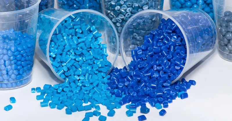
Material Selection: Consider shrinkage rates (amorphous vs. crystalline) and flow characteristics.
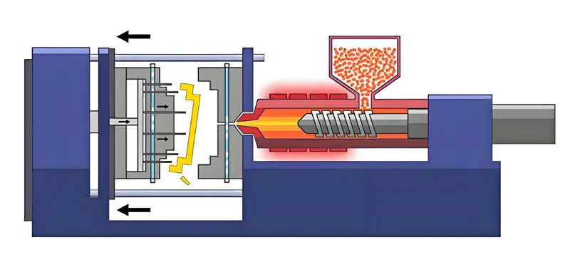
- Injection Molding Process:
- Filling: Molten plastic flows through the thicker walls and into the thinner rib channels. Flow resistance in thin ribs needs adequate pressure.
- Packing: Pressure is maintained to compensate for shrinkage as the plastic solidifies. This phase is critical at the wall-rib intersection.
- Cooling: The thicker intersection of wall and rib cools slowest. The 40-60% rule helps mitigate excessive differential cooling, reducing sink and warp. Cycle time is influenced by the thickest section.
- Ejection: Proper draft on ribs is essential for clean part removal without damage.
- Quality Control: Inspect parts for sink marks opposite ribs, warpage, and complete filling of rib features.
Material Compatibility Explanation:
The ideal ratio can be influenced by material properties:
-
Amorphous Plastics (e.g., ABS, PC, PS): Lower, more uniform shrinkage. Can sometimes tolerate ratios closer to 60%, but sink is still a primary concern, especially on appearance surfaces.
-
Semi-Crystalline Plastics (e.g., PP, PE, Nylon, Acetal, PBT): Higher, more anisotropic (direction-dependent) shrinkage. More prone to sink and warp. It’s generally safer to stay closer to the 40-50% range for these materials, especially if unfilled.
-
Filled Plastics (e.g., Glass-Filled Nylon): Fillers reduce shrinkage but can increase viscosity (affecting flow into thin ribs) and introduce anisotropic behavior leading to warp. The 40-60% rule is still a good starting point, but CAE analysis becomes more valuable.
IV. Practical Tools Level: Enhancing Content Operability
Here are actionable tools for designers and engineers.
Rib Design Checklist:
-
Ratio: Is rib thickness between 40% and 60% of the nominal wall thickness? (Start at 50%).
-
Height: Is rib height ≤ 3x the nominal wall thickness?
-
Draft: Is there a minimum draft angle of 0.5° per side (more is better)?
-
Base Radii: Is there a generous radius (≥ 0.25x wall thickness) where the rib meets the wall?
-
Spacing: Is the distance between parallel ribs ≥ 2x the nominal wall thickness?
-
Thickness Consistency: Avoid abrupt changes in thickness.
-
Aesthetics: Is the surface opposite the rib non-critical, or have steps been taken (lower ratio, simulation) to minimize sink?
-
Flow Orientation: Are ribs oriented parallel to the anticipated flow path where possible?
-
Crossings: Are intersecting ribs avoided or carefully designed (cored out underneath) to prevent thick mass concentrations?
Process Selection Decision-Making (Ratio Focus):
-
Decision Point: Determining the specific Rib-to-Wall Ratio.
- Start Point: Begin with a target ratio of 50%.
- Aesthetic Check: Is the surface opposite the rib a critical appearance surface?
- Yes: Lean towards 40-50%. Consider multiple thinner ribs instead of one thicker rib. Use Moldflow analysis to verify sink depth.
- No: 50-60% might be acceptable, but still verify potential sink/warp impact.
- Material Check: What type of material?
- Semi-Crystalline (PP, Nylon, etc.): Be cautious. Stick closer to 40-50%.
- Amorphous (ABS, PC, etc.): Can often tolerate 50-60% if structurally necessary, but monitor sink potential.
- Structural Requirement Check: Is the rib under significant load?
- High Load: Aim for the higher end (55-60%) if sink/aesthetics allow. Ensure generous base radii. Consider material reinforcement (e.g., glass fill) or alternative designs (gussets, multiple ribs). FEA may be needed.
- Low Load: Stay conservative (40-50%) to prioritize moldability and aesthetics.
- Manufacturability Check: Is the rib very tall or thin, potentially causing filling or cooling issues?
- Yes: Consult with your mold maker (like ZetarMold!). May need design adjustments (thicker rib base, shorter height, better flow path) or process optimization.
V. Extension Level: Building a Knowledge Network
Understanding the rib-to-wall ratio connects to a broader network of design and manufacturing knowledge.
Related Technology Navigation:
-
Upstream:
- Part Design (CAD): Where the initial geometry, including ribs, is created.
- Material Selection: Properties dictate shrinkage, flow, and strength, influencing rib design.
- Finite Element Analysis (FEA): Simulates structural performance under load, determining if and where ribs are needed.
- Moldflow Analysis (CAE): Simulates the molding process itself, predicting defects related to rib design before mold creation.
- Core Process:
- Injection Molding: The manufacturing process where rib design directly impacts success.
- Downstream:
- Mold Making: Translating the rib design into physical tooling.
- Process Optimization: Adjusting molding parameters (pressure, temperature, time) to accommodate rib features.
- Quality Control: Inspecting for rib-related defects (sink, short shots, warp).
- Part Assembly: Ribs can interfere or aid in assembly processes.
- Related Design Features:
- Bosses: Often require supporting ribs or gussets.
- Gussets: Triangular ribs used to support walls or bosses.
- Coring Out: Removing material from thick sections (opposite approach to adding ribs).
- Draft Angles: Essential for all molded features, including ribs.
- Wall Thickness Uniformity: A core principle that rib design supports.
Conclusion: Balancing Strength and Manufacturability
The ideal rib-to-wall thickness ratio, generally recommended to be between 40% and 60%, is a critical guideline in injection molding design. It represents a careful compromise between adding necessary strength and stiffness while minimizing the risk of manufacturing defects like sink marks and warping.
Adhering to this guideline, along with other best practices for rib height, draft, radii, and spacing, is key to producing high-quality, cost-effective injection molded parts. Remember that material choice and aesthetic requirements play a significant role in refining the optimal ratio for your specific application.
-
Explore how rib design can improve the strength and durability of plastic parts in manufacturing. ↩
-
Understanding this ratio is crucial for preventing defects in molded parts and optimizing design. ↩
-
Learn about various molding defects and effective strategies to avoid them in your designs. ↩
-
Exploring Nominal Wall Thickness can help you grasp its foundational role in achieving optimal part performance and material efficiency. ↩
-
Learning about Rib Thickness can enhance your knowledge of structural performance and material savings in design processes. ↩
-
Understanding the Rib-to-Wall Ratio is crucial for preventing molding defects and ensuring structural integrity in design. ↩
-
Exploring structural rib types can provide insights into their applications and benefits in various engineering fields. ↩
-
Learning about rib design best practices can improve your engineering projects and ensure structural integrity. ↩
-
Understanding the factors influencing rib design can enhance your knowledge of structural engineering and material selection. ↩